


I've reached an exciting milestone in my Cart-Pole journey: our very first successful swing-up of a single pendulum! Today, I will share the progress we've made during the recent weeks. I will explain everything about the physical model, the updated mathematical model, the control system and communication layers that are being used, as well as the user interface. Afterwards, I will show you some of the recent results, a video of an actual Swing-Up and reveal what we'll work on during the upcoming weeks. As always, the code is available on GitHub.
Physical Model
During the past summer months, a friend and I have been developing the hardware for the physical model of the Cart-Pole system. The Cart is mounted on an aluminium profile track and is driven by a timing belt. A main microcontroller (ESP32) controls the system and talks to the user's computer. There are also some worker ESP32s scattered around the assembly.
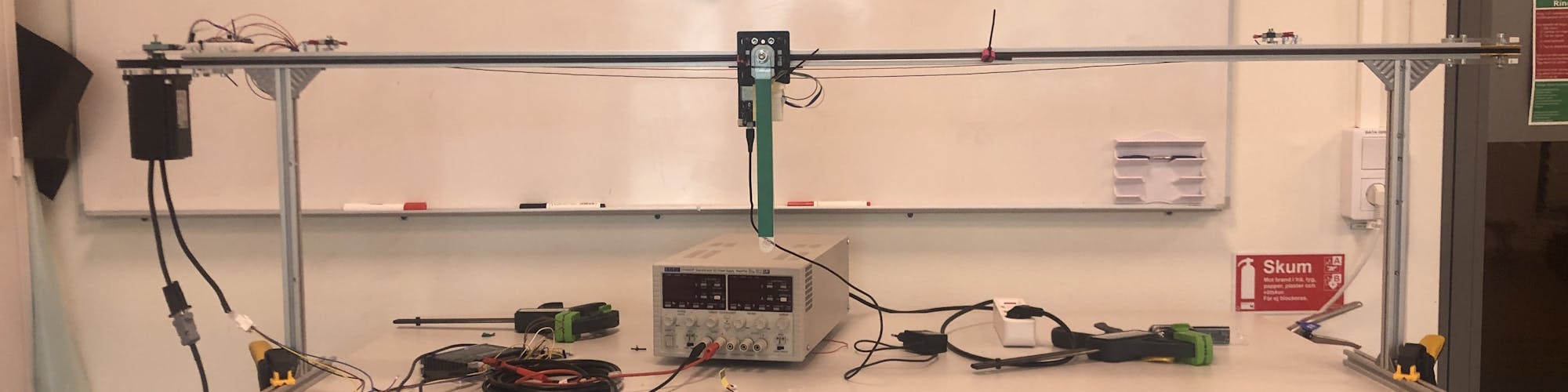
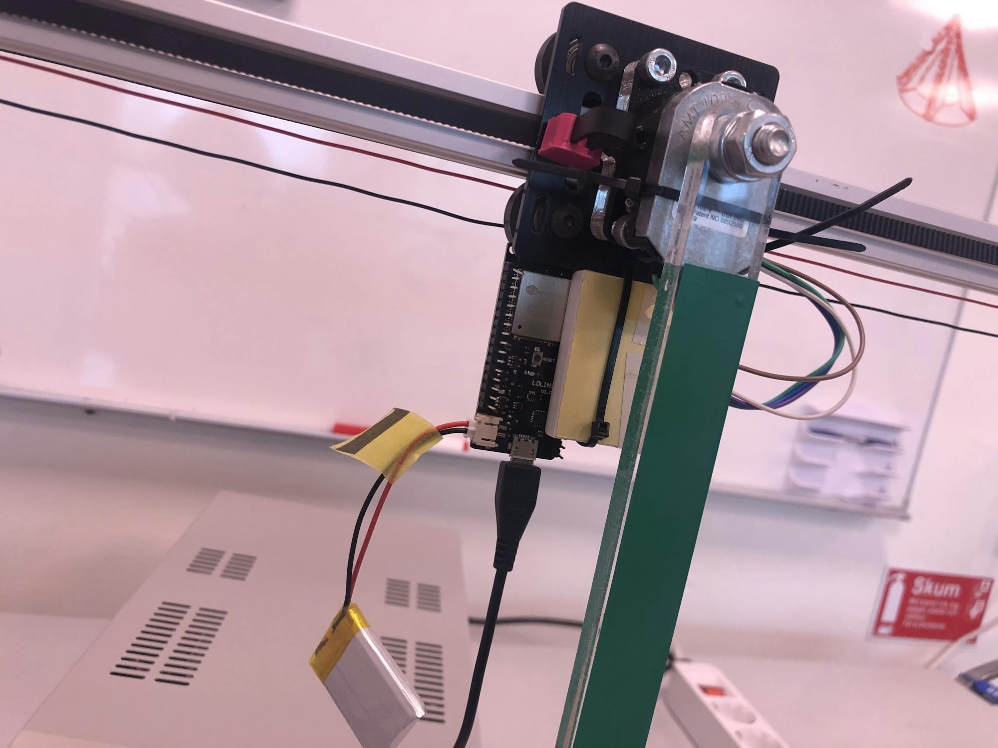
There is an inverted pendulum (Pole) that rotates freely around the Cart with a bearing. The rotation/angle of the Pole is measured using an incremental encoder (AMT102-V). The data pins of the encoder are read using interrupt pins on a worker ESP32. The ESP32 sends the current angle of the Pole to the main ESP32 wirelessly using ESP-NOW. Both the encoder and the ESP32 are powered by a 3.7 V battery. The reason for using wireless communication and battery power is to make the design of the Poles less complex. For example, using wired encoders would require using slip rings and increasing the number of poles would mean changing the design. Using "smart" Poles instead makes the system modular as you can have a single design of a Pole but use any number of Poles in the system.
The timing belt is driven by a stepper motor (CS-M22430) with an inbuilt encoder. However, the encoder is not working properly so we are planning on replacing it with an incremental encoder of the same model used in the Pole. There are also end stops on each end of the track. These are not yet connected but will be used for homing the Cart and for stopping the motor if it spins out. The end stops and motor encoder are all connected to another worker ESP32 that, in the future, will send the rotation of the motor and the end stop signals to the main ESP32.
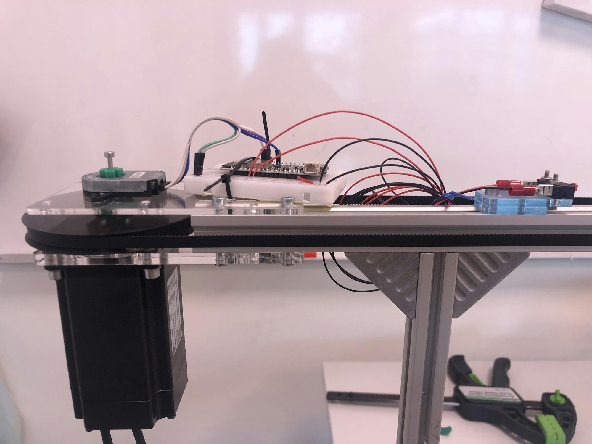
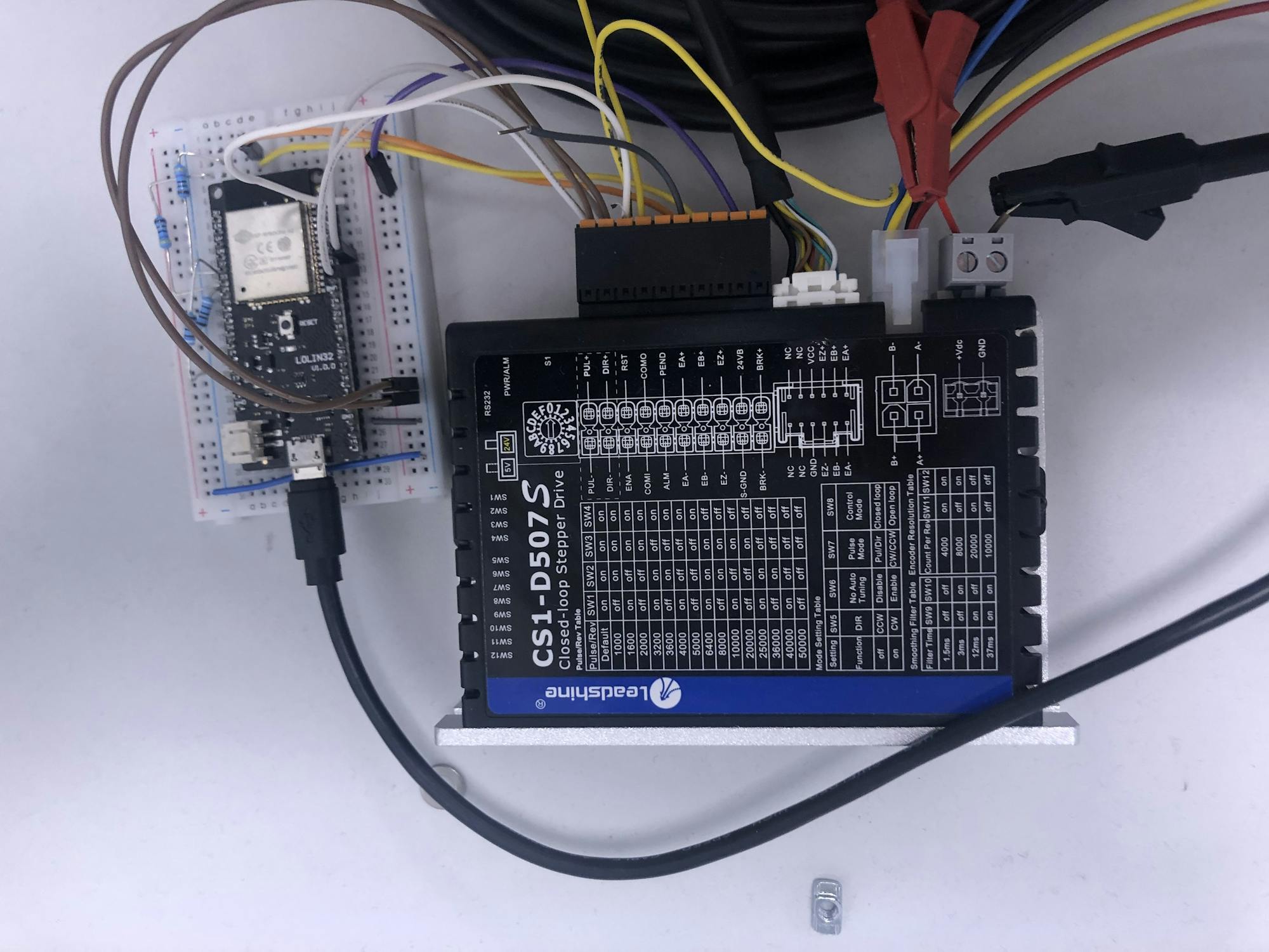
The stepper motor is driven by a stepper motor driver (CS1-D507S) that is hooked up to a 48 VDC power supply and is connected to the main ESP32. The ESP32 tells the motor which speed it should have using the AccelStepper library. The user's computer communicates to the ESP32 using serial and sends the desired acceleration of the motor. The ESP32 in turn integrates the acceleration to a velocity that it sends to the motor driver.
Controller and User Interface
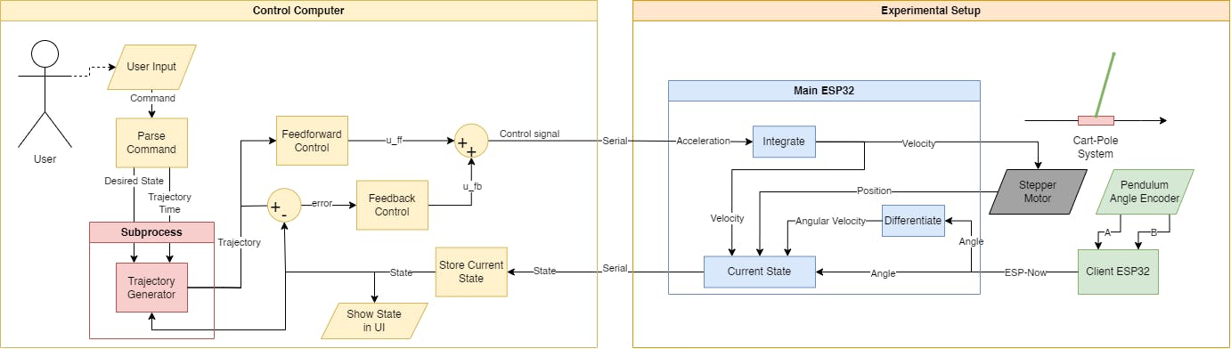
The control system builds on the technologies that have been used previously in the simulations. The control scheme uses direct collocation for generating trajectories, finite-horizon LQR for trajectory stabilization, and infinite-horizon LQR for balancing. The controller sends control signals, i.e. the desired acceleration of the stepper motor, and receives the current state of the system from the main ESP32 via serial communication. The controller runs a CartPoleEnv that stores the data and shows a virtual version of the Cart-Pole system.
The user can choose among several commands, such as sending a cosine signal or simple position tracking, but we'll stick to the trajectory command for simplicity's sake. The user inputs the desired state (position of the cart and if the pendulum should be up/down) and how long the trajectory will take. The desired state and time are used to generate an optimal trajectory using CasADi. This is done in a separate process using Python's multiprocessing library so that the main thread can keep sending control signals to the ESP32. The optimal states are then linearized and discretized and used to calculate the finite-horizon LQR gains, as well as to calculate the error during the trajectory. The optimal feedforward control plus the feedback control, calculated using the error and LQR gains, is sent to the main ESP32 to perform the trajectory. The trajectory controller is shown below.
Mathematical Model and System Identification
As usual, there are some revisions to the mathematical model. Using the control scheme with the physical model worked well when balancing the inverted pendulum. This suggests that the dynamics were quite accurate at the equilibrium points. However, the generated trajectories and feedforward control made the system unstable. This made us doubt the accuracy of our current model, so we went looking for a better one.
Luckily for us, Tobias Glück et al. [1] had already managed to balance a triple pendulum on a cart with their mathematical model. Their equations did however not provide explicit solutions for the pendulums' angular accelerations, which had to be solved using Lagrangian mechanics. To solve for the angular accelerations, as well as the control force which can be used as a constraint, we used SymPy. For faster calculations, you generally want to use numerical expressions instead of symbolic ones. To achieve this, we converted the SymPy expressions to CasADi expressions using a sympy2casadi function by Joris Gillis [2]. Using our CasADi expressions, we can perform calculations easily and quickly in our controller.
We already know a lot about the parameters of our system. The mass of the Cart and Pole, as well as the inertia, length and distance to the centre of mass of the Pole can all be measured. The only unknown parameter is the viscous friction in the joint of the Pole. This could be estimated using for instance linear regression, but at the moment the friction has been estimated empirically.
Current Results
The physical model was connected to the control scheme and the Pole was set to do some swing up/down maneuvers and position following along the track. The result can be seen in the video below.
And it works super well!
Future Development
Next up, I will work on system identification, which will be important when we add another pendulum. My friend is working on making a modular Pole design. Hopefully, the end stops and the motor encoder will all be up and running as well. But that's all for now, thanks for reading!
-SL
References
[1] T. Glück, A. Eder, and A. Kugi, "Swing-up control of a triple pendulum on a cart with experimental validation," Automatica, vol. 49, no. 3, pp. 801-808, Elsevier, 2013, doi:10.1016/j.automatica.2012.12.006.
[2] J. Gillis, "sympy2casadi," [Gist], GitHub, August 13, 2023. URL: https://gist.github.com/jgillis/80bb594a6c8fcf55891d1d88b12b68b8