


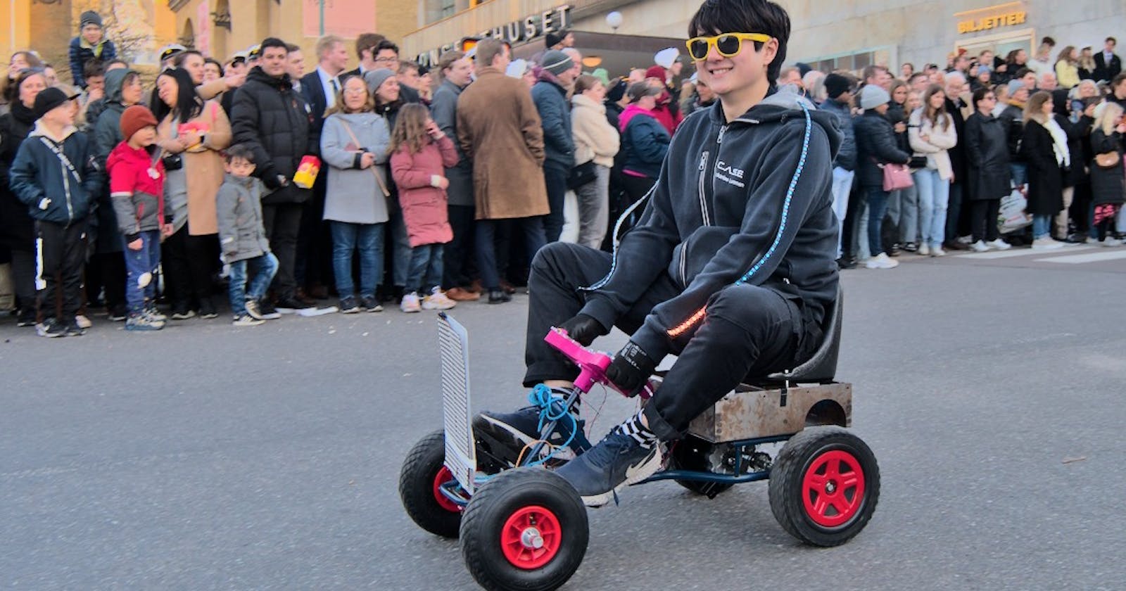
(Me driving my little guy. Photo: Dennis Holmström, zfoto.ztek.se)
Heads up, this blog post will be less professional and a bit more personal. For the past two months, I've been neck-deep in working on my Bachelor's thesis (which I will hopefully get to write about soon). At the same time, I've been working on a small electric vehicle, or EV for short. It is the first vehicle I've ever built, and it has been as fun as it has been stressful. Keep in mind, the pictures that I took for the documentation were lost to my old phone. The pictures in this article were all taken after the EV was completed.
Why build an EV?
Besides being a fun project, it also has a fun purpose. I'm a student at Chalmers University of Technology in Gothenburg, and every year on the 30th of April we celebrate Valborg in Sweden. On this day, since 1909, Chalmers students have been putting on a parade in Gothenburg called the Chalmers Cortège. Students have 10 days to build theatrical displays called equipages (Swedish: ekipage) that are put on top of large trucks and driven through the city. Besides equipages, students also build theatrical numbers that are not put on trucks. These vehicles are called single numbers (Swedish: lösnummer). Most of them are gas driven but an increasing number are becoming electric.
I am a board member of Chalmers Autonomous Systems and Electronics Association (CASE Association for short) and we love building EVs. The association is quite young so last year's Cortège was the first we could participate in. Last year we drove three single numbers, one of which broke down. This year, we wanted to go BIG. So, four of the board members (including me) plus two previous board members decided to build a vehicle each.
Back in September of 2022, my friend and fellow CASE board member suggested the idea of buying a pedal car for kids. We ended up buying one each and started to make plans for electrification. In my possession, I had a brushed DC motor for electric bicycles, a mount for the motor and two wheels mounted on an axle that I had received from my friend. The axle and DC motor had gears in place for a chain drive. This sealed the fate of my EV to use a chain drive, which would come to haunt me for the rest of the month.
Structure and Construction
The pedal car was small and in rough shape when I bought it. Noticeably, the seat was quite low and uncomfortable to sit in. I also needed a space to place the electronics and batteries in, as well as a platform to attach the motor mount. Looking through the metal scraps in the CASE lab like the little rat I am, I found a rusty and poorly welded steel box that was perfectly suited for my needs. Using a bench drill press, I drilled six holes into the bottom plate of the box, through which I could fit M6 screws. These screws, along with M6 nyloc nuts, were used to fasten the steel box onto the pedal car. I also drilled a couple of holes on the top side of the box to fasten the seat.

Another big flaw with the original pedal car was the wheels. The small plastic wheels did not provide enough grip force, couldn't handle off-road travel, and were super ugly. Luckily, I received a wheel axle along with two wheels from my friend. The axle included a chain drive gear and was mounted on the back of the car. To replace the steering wheels, I bought two rubber wheels with an inner diameter of 200 mm. However, the old steering wheels had an inner diameter of 100 mm. To attach the new wheels, I procured an aluminium rod with a diameter of 200 mm to create a spacer. Using a bench drill press, I drilled a hole along the axis of the rod's length with a diameter of 100 mm and a depth of 60 mm, which was deep enough to fit the steering axle. On the other end of the hole, across the rod, I drilled a 5.5 mm hole to fit an M5 screw to fasten the wheel onto the spacer. Two of these spacers were constructed, one for each wheel.

Finally, the motor mount made of a steel plate needed to be attached. The goal with the motor mount was to be able to tension the chain and to have it as close to the wheel axle as possible, to minimize slackness in the chain. To accomplish this, an aluminium profile was attached using M4 screws underneath the steel box. Holes with a diameter of 4.5 mm were drilled into the motor mount so that it could be fastened to the profile using M4 screws and T-nuts. By doing this, the motor mount can be slid across the length of the profile to tension the chain. When the chain is sufficiently tensioned, the T-nuts can be fastened.

Motor and Electronics
The motor that was used was a brushed DC motor made for electric bicycles (MY1016Z2). The DC motor has a max voltage of 24 V and a max power of 250 W. To power the motor, I used a 7S (25.9 V) LiPo battery. The battery was quite small and had a low charge, but it was convenient and I didn't bother buying a new one. The motor and the battery both used XT90 connectors which I soldered on. For safety reasons, I added a toggle switch that could break the electrical connection to the battery.

To control the speed and direction of the motor, a simple H bridge that can handle the high power requirement will suffice. The H bridge came in the form of a brushed electric speed controller (ESC) with an input voltage of 12-35 V and a max current of 120 A. The ESC has a cable that can power electronics using 5 V. The speed and direction of the motor can be controlled using a PWM signal. Sending a signal with a pulse width of 1500 μs makes the motor stay still. Increasing the pulse width will increase the angular velocity until the maximum pulse width of 2200 μs. Decreasing the pulse width will instead increase the angular velocity in the reverse direction until reaching the minimum pulse width of 800 μs.

Interestingly, when the ESC is in neutral mode at 1500 μs the controller actively tries to decelerate the motor to a complete standstill. This causes the motor to brake way too fast which ends up making the chain pop off. To decelerate without destroying the chain, instead of going directly to 1500 μs, the ESC is given a signal of 1600 μs. This makes the car decelerate normally. Naturally, if the car decelerates when going in reverse a signal of 1400 μs is sent, using the same offset of 100 μs.
To drive the car, the driver needs a way to control the EV that is robust and reliable. For accelerating, I took inspiration from real cars and bought a cheap gas pedal from Amazon. The gas pedal uses a Hall effect sensor that can be read as an analog signal by a microcontroller. The analog signal is supposed to be in the range of 0-5 V, but after testing with a multimeter, the real range is around 0.9-4.2 V.

To steer the EV, I found a race car steering wheel (bremme, https://www.thingiverse.com/thing:4058270) that suited well for my purposes. I designed a connector for the steering wheel that fits the previous steering wheel's shaft. The steering wheel has several installation holes for push buttons. The EV ended up having two push buttons, one for the parking brake and one for driving in reverse.

Software and Control
To get user input and control the ESC, I used an Arduino Nano microcontroller which was connected to the other electronic components with a breadboard. The microcontroller receives power from the ESC and has connections for the gas pedal, the two push buttons and to control the motor.

When driving the EV, two states can be toggled on and off: the parking brake and the reverse gear. If the parking brake is engaged, the ESC is put in brake mode and engaging the gas pedal won't have any effect. Naturally, if the reverse gear is engaged, accelerating makes the car go backward instead. To toggle these states, the associated push button for each respective state can be pressed. In the code, this is implemented using boolean variables for the states. A state is toggled when its associated button is pressed and it wasn't pressed in the last loop iteration.
To drive the EV forward and backward, the strength of the signal from the gas pedal is read using Arduino's analogRead(), which is a 10-bit value between 0 and 1023. This value is then mapped from the voltage range that was found earlier (converted to 10-bit numbers) to the pulse width of the signal that is sent to the ESC. Since it is assumed that the car is accelerating, the signal is mapped to a pulse width between 1600 μs (neutral pulse width plus the deceleration offset) and 2200 μs. Afterward, the algorithm checks if the EV is in reverse gear mode. If so, the pulse width is reversed to the range of 800-1400 μs.
To accelerate and decelerate the EV without popping off the chain, the desired pulse width, or throttle, is not sent directly to the ESC. Before the car accelerates, the state of the parking brake is checked. If the parking brake is enabled, the neutral signal of 1500 μs is sent to the ESC. Otherwise, if the current throttle of the ESC is lower than the desired throttle, the current throttle is increased by a constant value of 10 μs. If the current throttle is higher than the desired, the current throttle is decreased by 10 μs. If the absolute difference between the current and the desired throttles is less than 10 μs, then the current throttle is set to be equal to the desired throttle. After updating, the new current throttle is sent to the ESC using Arduino's Servo library. This is done for every loop cycle and ensures that the EV doesn't accelerate or decelerate too quickly.
#include <Arduino.h>
#include <Servo.h>

#define ESC_PIN 9 // ESC signal pin
#define PEDAL_PIN A0 // potentiometer signal pin
#define BRAKE_PIN 3 // parking brake signal pin
#define REVERSE_PIN 4 // reverse gear signal pin

const int MIN_PEDAL = 190; // set minimum pedal value
const int MAX_PEDAL = 860; // set maximum pedal value

Servo esc; // create a Servo object for the ESC
const int PWM_DUTY_MIN = 800; // set PWM duty cycle for full reverse (in microseconds)
const int PWM_DUTY_MAX = 2200; // set PWM duty cycle for full forward (in microseconds)
const int PWM_DUTY_NEUTRAL = 1500; // set PWM duty cycle for neutral/stop (in microseconds)
const int PWM_DUTY_NEUTRAL_OFFSET = 100; // offset for neutral position when parking brake is off

void setup() {
  // set pin modes
  pinMode(PEDAL_PIN, INPUT);
  pinMode(BRAKE_PIN, INPUT);
  pinMode(REVERSE_PIN, INPUT);

  // attach ESC and put it in neutral position
  esc.attach(ESC_PIN); // attach ESC signal to pin 9
  esc.writeMicroseconds(PWM_DUTY_NEUTRAL); // set to neutral/stop position
}

// Throttle
int pedal_value;
int desired_throttle = PWM_DUTY_NEUTRAL;
int current_throttle = PWM_DUTY_NEUTRAL;

const int THROTTLE_STEP = 10;

// Reverse gear state
bool last_pressing_reverse = false;
bool is_pressing_reverse = false;
bool reverse = true;

// Parking brake state
bool last_pressing_brake = false;
bool is_pressing_brake = false;
bool brake = true;

void loop() {
  // Read the pedal and push buttons
  pedal_value = analogRead(PEDAL_PIN);
  is_pressing_reverse = digitalRead(REVERSE_PIN);
  is_pressing_brake = digitalRead(BRAKE_PIN);

  // Update the reverse gear state
  if (is_pressing_reverse && !last_pressing_reverse) {
    reverse = !reverse;
  }
  last_pressing_reverse = is_pressing_reverse;

  // Update the parking brake state
  if (is_pressing_brake && !last_pressing_brake) {
    brake = !brake;
  }
  last_pressing_brake = is_pressing_brake;

  // Map the pedal value to the desired throttle and constrain it
  desired_throttle = map(pedal_value, MIN_PEDAL, MAX_PEDAL, PWM_DUTY_NEUTRAL+PWM_DUTY_NEUTRAL_OFFSET, PWM_DUTY_MAX);
  desired_throttle = constrain(desired_throttle, PWM_DUTY_NEUTRAL+PWM_DUTY_NEUTRAL_OFFSET, PWM_DUTY_MAX);

  // Reverse throttle if reverse enabled
  if (reverse) {
    desired_throttle = PWM_DUTY_NEUTRAL - (desired_throttle - PWM_DUTY_NEUTRAL);
  }

  // Set current throttle
  if (brake) {
    // If the parking brake is enabled, brake the motor
    current_throttle = PWM_DUTY_NEUTRAL;
  } else {
    // Else, increase/decrease the throttle to the desired throttle
    if (abs(current_throttle-desired_throttle) < THROTTLE_STEP) {
      current_throttle = desired_throttle;
    } else if (current_throttle < desired_throttle) {
      current_throttle += THROTTLE_STEP;
    } else if (current_throttle > desired_throttle) {
      current_throttle -= THROTTLE_STEP;
    }
  }

  // Write throttle to ESC
  esc.writeMicroseconds(current_throttle);

  delay(50);
}
The Cortège Day
On the same day as the parade, some last-minute changes were added. This was done as I felt like the EV wasn't cool or unique enough in comparison with the other vehicles. Therefore, I added two big 32x8 RGB LED pixel matrices to the front of the vehicle. This was done hastily by connecting the matrices and an ESP32 microcontroller to the 5 V power on the breadboard. One of the digital pins of the ESP32 was connected to the data in-pins on one of the matrices. This matrix then connected its data out-pin to the data in-pin on the other matrix. To program the matrices, the ESP32 was booted with a WLED web server (Schwinne, https://kno.wled.ge/), which a friend recommended to me. This is a super easy-to-use library that can be used to control LED strips and matrices from your phone or computer.

Finally, the time of reckoning arrived and issues started appearing. The chain loosened and popped off as usual. Luckily, a friend spotted a loose screw that was the root of the problem. The 2-hour drive went surprisingly well. The chain stayed on, the mechanical brake which I had never used worked flawlessly and I didn't hit any kids! Unfortunately, the LED matrix on the front of the car had trouble connecting to my phone, so the only color that worked was the default orange. The small LiPo battery that I used eventually died. This was expected however since the battery had a low charge so my friend had brought a rope along. The rope was used to tow me for the trip back to base. Overall, the Cortège was a success.

(The money shot. Photo: Måns Lundberg, zfoto.ztek.se)

Takeaways
As I mentioned earlier, the chain drive wasn't the most optimal choice. Throughout the whole building process, the chain kept popping off the gears. I also had trouble joining chain links together as this caused them to be stiffer which affects the overall performance of the chain. Tensioning the chain also proved to be difficult. The way the chain could be tensioned using the motor mount did work, but it required 1-2 people to hold the parts while another fastened the screws. The steel box and wheel axle tended to flex while driving which caused the chain to loosen during extended drives.
If there's anything I've learned it is to use good motors when designing vehicles. Brushed DC motors are fine, but there are better alternatives. A popular choice is to use hub motors that are already integrated into the wheels. These have high torque and don't require a belt or chain to be driven. Steering a vehicle with hub motors is a bit different as differential drive is often used, which can require more skillful turning. They are also usually not brushed DC motors and therefore require a more complex and expensive motor controller. However, the benefits are that the development time is significantly decreased since you don't have to worry about developing a chain or belt drive.
Lastly, next time I will focus on building a vehicle with a fun and wacky concept. The car I chose to modify was a simple pedal car but I think it would have been way more fun to create, for instance, a drivable toilet or couch or something. Unfortunately, that will have to wait until next year.